OS — Process

A Process is an instance of a program being executed by an OS. Ex: when a user opens a new application like a browser, the OS creates a new process for that application.
The OS keeps track of each process using Process Control Block (PCB).
PCB is a data structure for a process. It holds information about a process, including the process id, the execution stack, the set of resources used by the process, and the program being executed.
typedef struct ListNode {
void *data; // Pointer to hold data (PCB, file, resource, etc.)
struct ListNode *next; // Pointer to the next node
} ListNode;
typedef struct PCB {
int *CPU_state; // Set of integers for CPU state, consist of various hardware registers and flags
char process_state; // Integer or char representing the process state
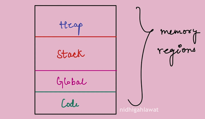
void *memory; // Pointer to memory (can be an address or data)
int *scheduling_information; // Set of integers for scheduling information
int *accounting_information; // Set of integers for accounting information
ListNode *open_files; // Start of a linked list of open files
ListNode *other_resources; // Start of a linked list of other resources
struct PCB *parent; // Pointer to the parent process
ListNode *children; // Start of a linked list of child processes
...
...
...
} PCB;See, as I said before PCB is just a data structure for a process. Also, it just hold some piece of code of an application that we running. This structure can wary OS to OS. The actual OS has tons of attributes for a PCB. Some OS (linux) call this as task, which denotes both process and thread data structure. For simplicity and easy understanding, we call this as PCB.
Now, we know PCB’s structure. Let get into the states, a process can be in.
Process States

1. New state:
A program in secondary memory is started for execution, the process is said to be in a new state.
2. Ready State
After being loaded into the main memory and ready for execution, a process transitions from a new to a ready state. The process will now be in the ready state, waiting for the processor to execute it. Many processes may be in the ready stage in a multiprogramming environment.
3. Run State
After being allotted the CPU for execution, a process passes from the ready state to the run state.
4. Terminate State
When a process’s execution is finished, it goes from the run state to the terminate state. The operating system deletes the PCB after it enters the terminate state.
5. Block or Wait State
If a process requires an Input/Output operation or a blocked resource during execution, it changes from run to block or the wait state.
The process advances to the ready state after the I/O operation is completed or the resource becomes available.
6. Suspend Ready State
If a process with a higher priority needs to be executed while the main memory is full, the process goes from ready to suspend ready state. Moving a lower-priority process from the ready state to the suspend ready state frees up space in the ready state for a higher-priority process.
Until the main memory becomes available, the process stays in the suspend-ready state. The process is brought to its ready state when the main memory becomes accessible.
7. Suspend Wait State
If a process with a higher priority needs to be executed while the main memory is full, the process goes from the wait state to the suspend wait state. Moving a lower-priority process from the wait state to the suspend wait state frees up space in the ready state for a higher-priority process.
The process gets moved to the suspend-ready state once the resource becomes accessible. The process is shifted to the ready state once the main memory is available.
The Context Switch
The CPU is always running one process at a time. Multiple processes can share a single CPU by taking turns. A context switch is the transfer of control from one process to another and may be triggered by the OS for scheduling reasons or caused by the inability of the current process to continue.
Each time one process stops executing to allow another one to resume, the OS must save all information about the stopped process. This information is restored when the process again gets a chance to run. The temporary interruption is fully transparent to the process.
The information that needs to be saved is called the CPU state. The CPU state consists of all intermediate values held in any CPU registers and hardware flags at the time of the interruption. One of the registers is the program counter, which determines the next instruction to execute after the process is restored.
Let’s discuss about how OS organizes PCBs.
Organizing PCBs
The OS must allocate and deallocate PCBs efficiently as processes are created and destroyed. Two ways exist to organize all PCBs:
- An array of structures. The PCBs are marked as free or allocated, which eliminates the need for any dynamic memory management. The main drawback is a lot of wasted memory space to maintain a sufficient number of PCB slots.
- An array of pointers to dynamically allocated PCBs. The pointer array wastes little space and can be made much larger than the array of structures. The drawback is the overhead of dynamic memory management to allocate each new PCB and to free the memory when the process terminates.
Avoiding linked lists
Linked lists require dynamic memory management, which is costly. The Linux OS has pioneered an approach that eliminates this overhead.
Instead of a separate linked list anchored in the parent’s PCB, the links are distributed over the child PCBs such that each points to the immediate younger sibling and immediate older sibling. The original 2 fields, parent and children, in the PCB of a process p are replaced by 4 new fields:
- parent: points to p’s single parent as before
- first_child: points to p’s first child
- younger_sibling: points to the sibling of p created immediately following p
- older_sibling: points to the sibling of p created immediately prior to p

Managing PCBs
The OS maintains all PCBs organized on various lists. A waiting list is associated with every resource and contains all processes blocked on that resource because the resource is not available. Another important list is the ready list (RL): A list containing all processes that are in the ready state and thus are able to run on the CPU. The RL also includes the currently running process. The RL maintains all processes sorted by their importance, which is expressed by an integer value called the priority. The RL can be a simple linked list where the priority of a process is the current position in the list. The RL can also maintain processes in different lists sorted by priorities.

The more the integer value, the more the priority is.
Operations on processes
The process creation hierarchy
A process creation hierarchy is a graphical representation of the dynamically changing parent-child relationships among all processes. The process creation hierarchy changes each time a process is created or destroyed.

Level 0:
- Root: When the OS starts, a Root process is created at Level 0. This Root process becomes the parent of all other OS processes.
Level 1:
- OS Processes (OS1, OS2, …): These are processes directly created by the Root process.
- Init: One of these OS processes becomes the highest ancestor of all user processes. In Unix-like systems, this process is called “Init.”
Level 2:
- User Processes (User1, User2, … UserN): Whenever a user logs in, a new user process is created at Level 2. The primary task of each user process is to communicate with the user.
Level 3:
- Child Processes of User Processes (Edge, Skype, …): Each user process can create child processes to perform various tasks, such as running a browser (Edge), communication tools (Skype), or other applications.
Process creation
When the currently running process initiates the creation of a child process, the OS executes a create process function, create(). The create process function allocates a new PCB, fills the PCB entries with initial values, and links the PCB to other data structures in the system:
- A new PCB is allocated. The PCB is uniquely identified by a pointer or an array index p.
- The fields cpu_state, memory, scheduling_information, and accounting_information are filled using the initial values supplied to the function as parameters.
- Assuming the state transition diagram consists of only the three states, running, ready, and blocked, the process state field is set to ready.
- The parent field of p is set to point to self, which is the calling process and thus the parent of p.
- In turn, p is inserted into the calling process’s list of children as a new child.
- The remaining fields are set to NULL, since at creation p has no children, no open files, and no other resources.
- p is inserted into the RL.
- The scheduler function is called to select the process to run. Depending on the priorities of the two processes, the scheduler could choose to start the new child process p or to continue the execution of p’s parent process.
- When the scheduler returns, the function returns the ID of the new child (p) to the calling process.
Process destruction
A process p can be terminated by the parent process by calling the function destroy(p). Completing all work or committing a fatal error also results in the process’s destruction. The destroy process function destroys a process by freeing the PCB data structure and removing any references to the PCB from the system.
Depending on the OS, the destroy function may also destroy all of the process’s descendants to prevent having “orphan” processes in the system. The destruction of the entire hierarchy of descendants is accomplished by calling destroy(c) recursively on all children c of p.
The destroy() function performs the following steps:
- After calling destroy(c) on all child processes, remove p from either the RL (when p is ready) or from the waiting list of a resource (when p is blocked).
- Remove p from the list of children of the calling process.
- Release all memory and other resources, close all open files, and deallocate the PCB.
- Call the scheduler to select the next process to run. The call must be made outside of the destroy(p) function to guarantee that the scheduler executes only once, after the entire hierarchy of processes has been destroyed, rather than as part of every recursive call to destroy(c).
In this article, we have learned about process structure, process states, context switching, how OSs organize processes, hierarchy, process creation and destruction.
Hope you have learned something new. Next week we will see about resources, one of the attributes of PCB (other_resources).
Thanks for reading the article. Happy learning.